Daniella Garcia-Loos
Peter Apps
AP Physics 2 🧲
61 resourcesSee Units
Electromagnetic Induction
Making Magnets from Electricity 🧙
Electromagnetic Induction is the process of using magnetic fields to produce a voltage. If that voltage is produced in a complete circuit, it can create a current. We've seen in the previous section that current moving through a wire creates a magnetic field, all we're doing here is reversing that process.
Take a few minutes to play around with this PhET simulation, especially the Pickup Coil Tab. What does it take to make the bulb light up?
Image created by the author using PhET
The magnet needs to be moving! Just like we needed a moving charge to create a magnetic field, we need a moving magnetic field to induce a potential difference.
Magnetic Flux 🌐
Flux is a very useful concept to help describe a wide variety of physics concepts. We're going to apply it here for magnetic fields, and if you take AP C: E&M we'll also use it to describe electric fields. Basically, flux describes how much of something goes through a given area.
We're going to imagine an area on the surface of a magnetized object. It doesn't matter what the object is. The magnetic flux (ΦB) is then described by how many magnetic field lines pass through the area. Generally, we define the area to be parallel to the magnetic field, since this simplifies the math. However, if we can't do that, we take the dot product between the area vector and the magnetic field to determine the flux.
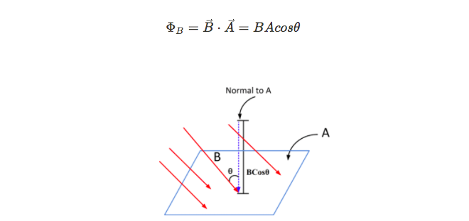
Image Courtesy of electricalacademia
B is the magnetic field strength, A is the area we're measuring the flux through, and θ is the angle between the magnetic field vector and the area vector. Looking at the units for the flux, we can see that it would be Tm^2, which is equivalent to a Weber (Wb)
Creating EMF
Since we know that a moving magnet causes a potential difference to appear in the simulation, we can attempt to model that mathematically. This can be done using Faraday's Law:

Faraday's law of induction is a principle in physics that describes the relationship between a changing magnetic field and the electric current induced in a conductor. It states that the induced electromotive force (emf) in a conductor is equal to the rate of change of the magnetic flux through the conductor.
Here are some key points about Faraday's law of induction:
- Faraday's law of induction is a fundamental principle in electromagnetism and is used to understand and analyze the behavior of induced currents in electrical and electronic circuits. It is a useful tool for predicting the behavior of electrical and electronic devices and circuits.
- Faraday's law of induction is based on the principle that a changing magnetic field will induce an electromotive force (emf) in a conductor. The induced emf is equal to the rate of change of the magnetic flux through the conductor. This relationship is described by the equation emf = -N*dΦ/dt, where emf is the induced emf, N is the number of turns in the conductor, Φ is the magnetic flux, and t is time.
- Faraday's law of induction is often used in conjunction with Lenz's law, which states that the induced current will always act to oppose the change in the magnetic field that caused it. Together, these laws describe the behavior of induced currents in electrical and electronic circuits.
- Faraday's law of induction is a key principle in the operation of generators, transformers, and other electrical and electronic devices that rely on induced currents. It is also used to understand and analyze the behavior of electromagnetic waves and to predict the behavior of electrical and electronic circuits.
- Faraday's law of induction is a consequence of the conservation of energy and the fact that energy can be converted from one form to another. It is based on the observation that a changing magnetic field can induce an electric current in a conductor.
Typically, you'll use the first section of the equation if you're asked generically about the scenario, the last section is if you're calculating the EMF in a loop of wire (ℓ) is the length of the loop and v is the velocity at which the loop is moving. For a more in-depth dive into where this equation comes from, check out the AP Physics C: EM Guide on this topic.
The change in magnetic flux causes an induced EMF. Looking at our definition of flux, we see that the magnetic flux can be changed in 3 main ways:
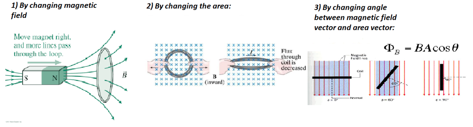
Image Courtesy of physics.stackexchange
What about the Direction of the EMF?
Lenz's Law deals with the negative sign in Faraday's Law. It gives us the direction of the induced EMF and lets us find the direction of the induced current, as well (you do remember the Right-Hand Rule, right?). In the simplest sense, Lenz's Law says that the induced EMF in a loop or wire will always oppose the change in magnetic flux that caused it.
The basic reasoning for this comes from the Law of Conservation of Energy. If the induced EMF was in the same direction as the flux, we would enter a positive feedback loop that would produce infinite EMF (and infinite energy).
Lenz's law is a principle in physics that describes the direction of the induced current in a conductor. It states that the induced current will always act to oppose the change in the magnetic field that caused it.
Here are some key points about Lenz's law:
- Lenz's law is a consequence of the conservation of energy and the fact that energy can be converted from one form to another.
- Lenz's law is used to understand and analyze the behavior of induced currents in electrical and electronic circuits. It is a useful tool for predicting the behavior of electrical and electronic devices and circuits.
- Lenz's law is based on the principle that the induced current will always act to oppose the change in the magnetic field that caused it. This means that the induced current will always act to reduce or eliminate the change in the magnetic field.
- Lenz's law can be used to predict the direction of the induced current in a conductor and to design and troubleshoot electrical and electronic circuits.
- Lenz's law is often used in conjunction with Faraday's law of induction, which states that the magnitude of the induced current is proportional to the rate of change of the magnetic field. Together, these laws describe the behavior of induced currents in electrical and electronic circuits.
For some simple DIY examples of Lenz's Law in action, check out this video by D!NG, or this one by Veritasium.
Ok, now let's take a look at a bunch of examples:
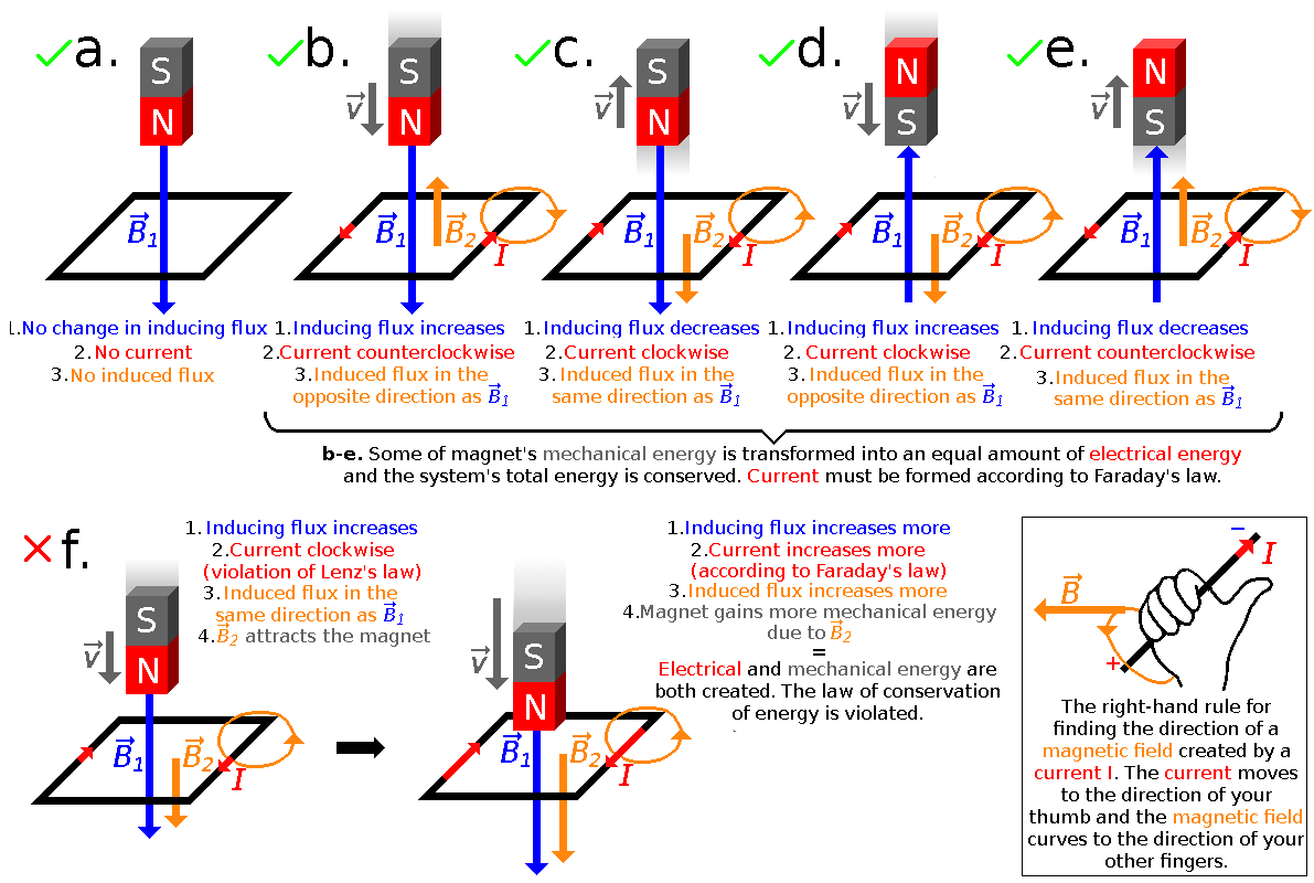
Image Courtesy of wikipedia
- In case (a) the magnet is stationary. There is no changing flux, so there is no current or opposing induced magnetic field.
- Case (b) shows the magnet falling. The flux is increasing because the magnetic field B1 is getting stronger, so there must be an induced magnetic force that opposes it B2 pointing upwards. Using the RHR, we can see that the induced current in the loop must be traveling CCW to produce this opposing field.
- Case (c) shows the reverse of case (b). The flux is decreasing because the magnet is moving away, so the induced magnetic field must be pointing in the same direction as B1 to counteract the weakening field. This induced field is created by the current traveling in a CW direction.
Practice Problems
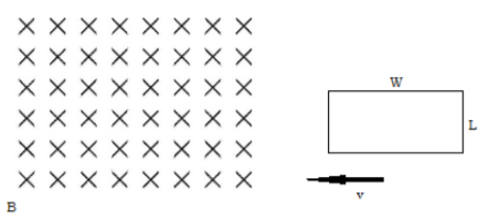
Image created by the author
- A loop of conducting wire with length L and width W is entering a magnetic field B at velocity v. What direction will the induced current travel in?
- What is the induced EMF in the wire?
- The loop of wire has a resistance of R. What is the value of the induced current?
Answers
- Counterclockwise, Use the Right Hand Rule
- ε = Bℓv
- I = ε / R = Bℓv / R
Browse Study Guides By Unit
💧Unit 1 – Fluids
🔥Unit 2 – Thermodynamics
⚡️Unit 3 – Electric Force, Field, & Potential
💡Unit 4 – Electric Circuits
🧲Unit 5 – Magnetism & Electromagnetic Induction
🔍Unit 6 – Geometric & Physical Optics
⚛️Unit 7 – Quantum, Atomic, & Nuclear Physics
📆Big Reviews: Finals & Exam Prep
📚Study Tools
Fiveable
Resources
© 2025 Fiveable Inc. All rights reserved.